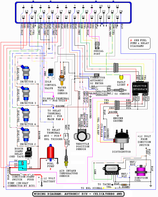

| Name: | Details: | Location: |
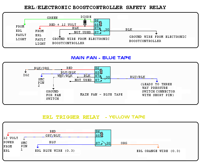
|
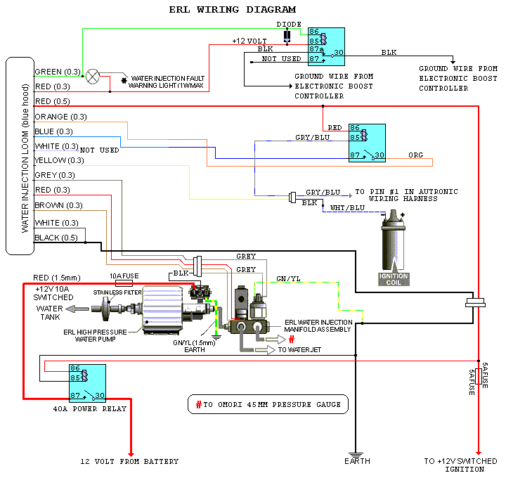
ERL
water injection
trigger relay |
Yellow tape - 4 pin relay pin 30 - orange = ERL pin 85 - grey/blue = SMC pin 1 pin 86 - red = +12 volt power pin 87 - blue = ERL |
Passenger side, at the right, near the other relays. |
|
ERL water injection, and electronic boost controller cut off relay |
Black tape - 5 pin relay pin 30 - black = ground wire EBC pin 85 - red = ERL fault light = +12 volt pin 86 - green = ERL fault light pin 87 - not used pin 87a - black = ground wire EBC There is a diode between pin 86 and 85, with the band towards the red wire |
Driver side, near the throttle pedal |
| Fan control |
Blue tape - 5 pin relay pin 30 - blue/black = fan pin 85 - blue/black = from SMC pin 2 pin 86 - red = +12 volt power pin 87 - not used pin 87a - black, into white/black = ground fan |
Near engine ECU |
|
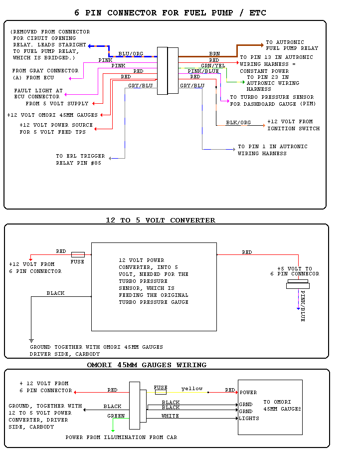
Autronic SMC fuelpump relay |
Red tape - 5 pin relay, no change over relay. pin 30 - brown = power to fuelpump pin 85 - red = SMC pin 25 pin 86 - blue = SMC pin 24 pin 87 - red, coming from blck/orange = power |
Near engine ECU |
| Reluctor interface | Connected between distributor, and Autronic SMC. Shielded wires from distibutor to reluctor interface |
Behind glove box. Glove box need to be removed |
| Name: | Details: | Location: |
| T-Vis relay |
Yellow tape - 4 pin relay pin 30 - black = ground, spliced in 5 volt converter ground wire pin 85 - red = +12 volt power, coming from power fan relay pin 86 - pink = SMC pin 15 pin 87 - blue/red = ground, coming from T-Vis valve |
Near engine ECU. |
| Power converter |
Power converter, converts +12 volt into 5 volt: 5 Volt is needed to feed the Turbo Pressure Sensor This TPS is feeding the stock dashboard turbo pressure gauge. Three wires: red = + 12 volt power, with fuse black = ground, made at the driver side, carbody. red into purple/blue to connector = + 5 volt power, to pim wire (pink/blue) |
Behind glove box. Glove box does not need to be removed |
| Omori 45mm gauges |
Electronic oil pressure gauge This gauge is feed by two sending units. One is for oil pressure, and one is for fuel pressure. The little switch at the right, in front of the gear stick lever is used for switching between the two sending units. Electronic oil temperature gauge This gauge is feed by two sending units. One is for oil temperature, and one is for water temperature. The little switch at the left, in front of the gear stick is used for switching between the two sending units. Mechanical oil pressure gauge This gauge is used to check the pressure of the ERL water injection Connector: green = power for illumination, into white Omori wire red = +12 volt power with fuse, into yellow, into red Omori wire. black = ground, into two black Omori wires. |
Connector is located behind the Omori gauges |
| Name: | Details: | Location: |
| Bosch igniter |
7 Pin Bosch Ignitor 1227 022 008 pin 1 - white/blue = negative from coil - white/blue = spliced to black wire for ERL - white/blue = spliced to black wire with 1K Ohm resistor inline to tachometer pin 2 - black = engine ground pin 3 - black = engine ground pin 4 - green = +12 volt coming from IG+ (blk/org) pin 5 - not used pin 6 - pink/white = pin 35 Autronic SMC pin 7 - not used |
Firewall, driver side |
| Bosch oxygen sensor |
Four wire Bosch Sensor - LSM11 0 258 104 002 123133 - 12v - Germany |
Downpipe |
| Diagnostic box |
Connected pins: IG = ignition signal (white/blue) +B = +12 Volt power (black/yellow) E1 = engine ground (brown) OX = oxygen sensor signal. This wire is still connected at the diagnostic box, but not at the Autronic SMC. |
Near firewall, driver side |